

PILING · SHORING · GROUND ENGINEERING

PILING, SHORING & GROUND ENGINEERING.

Al Watad Foundation provides piling, shoring, deep foundation and soil improvement services across the UAE. Explore methods for commercial, residential, industrial and infrastructure projects, with installation stages and detailed engineering references.

Choose a category or open any method below.

Bored piles

Bored piles

Cast-in-situ reinforced concrete piles transfer structural loads to suitable bearing strata.

Method, design checks & enquiry
Bored piles — system arrangement123
1Reinforced concrete shaft2Load transfer to ground3Bearing stratum
01

Drill & support

Drill with casing or support fluid where required; inspect the bore and clean the base.

02

Reinforce & concrete

Lower the reinforcement cage and place concrete by the approved method, including tremie placement where required.

03

Test & verify

Maintain installation records and complete specified integrity and load tests.

Design checks: ground report, groundwater, adjacent structures, access and project-specified verification.

Contiguous pile walls

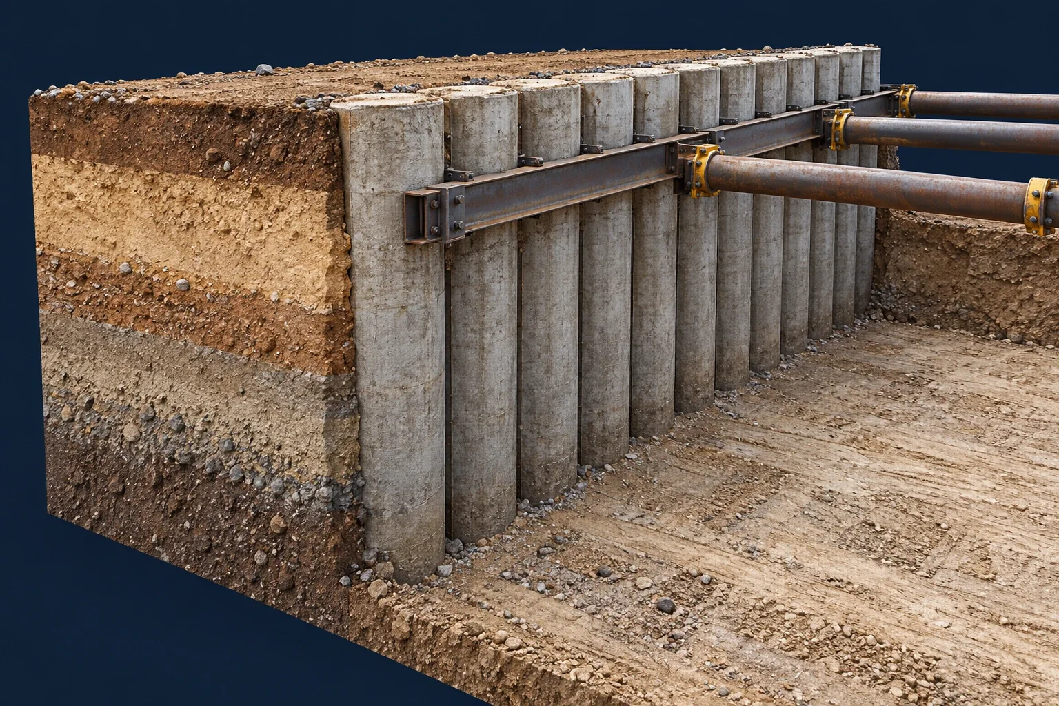
Contiguous pile walls

Closely spaced bored piles form an excavation-retention system, coordinated with the ground conditions and temporary support design.

Method, design checks & enquiry
Contiguous pile walls — system arrangement123
1Closely spaced piles2Gaps between piles3Retaining wall alignment
01

Set out & install

Set out pile positions and install the wall to the approved design.

02

Excavate in stages

Coordinate excavation lifts with the specified supports and groundwater controls.

03

Inspect & monitor

Review installation records and the specified monitoring results.

Design checks: ground report, groundwater, adjacent structures, access and project-specified verification.
Continuous flight auger (CFA) piles

Continuous flight auger (CFA) piles

A continuous auger supports the bore; concrete or grout is pumped through the hollow stem during withdrawal.

Method, design checks & enquiry
Continuous flight auger (CFA) piles — system arrangement123
1Continuous auger2Concrete during withdrawal3Reinforcement insertion
01

Continuous drilling

Drill to the specified depth with the continuous auger.

02

Withdrawal & pumping

Coordinate withdrawal with delivery pressure and volume to maintain the shaft.

03

Reinforce & check

Install reinforcement as specified; review installation data and required tests.

Design checks: ground report, groundwater, adjacent structures, access and project-specified verification.
Controlled modulus columns (CMC)

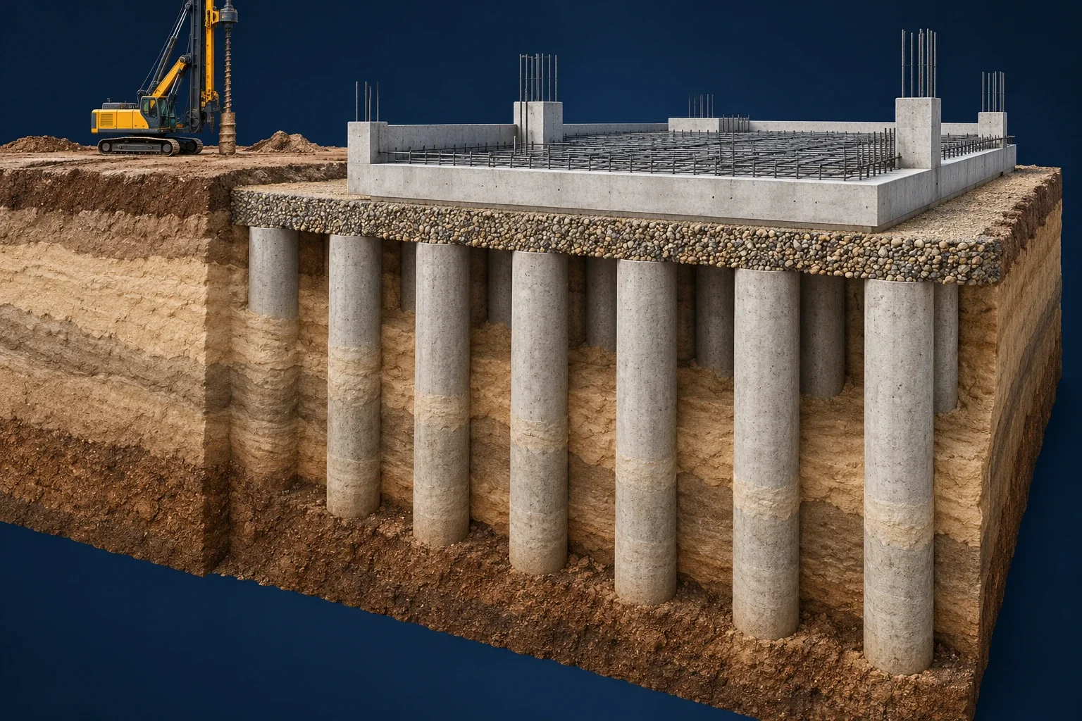
Controlled modulus columns (CMC)

A ground-improvement approach using designed inclusions, coordinated with the load-transfer arrangement and project acceptance criteria.

Method, design checks & enquiry
Controlled modulus columns (CMC) — system arrangement123
1Rigid inclusions2Load-transfer platform3Surrounding ground
01

Design the treatment

Review ground conditions and the approved inclusion and load-transfer design.

02

Install inclusions

Install the elements using the specified equipment and controlled sequence.

03

Verify performance

Maintain installation records and undertake project-specified verification.

Design checks: ground report, groundwater, adjacent structures, access and project-specified verification.
Dewatering

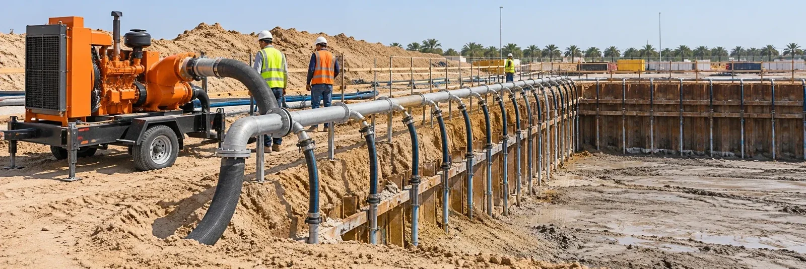
Dewatering

Deep wells and wellpoints manage groundwater for excavation with discharge and settlement controls.

Method, design checks & enquiry
Dewatering — system arrangement123
1Pumping well2Lowered groundwater level3Controlled discharge
01

Assess groundwater

Review permeability, water levels, drawdown and discharge arrangements.

02

Install & operate

Install selected wells or wellpoints, pumps and standby provision.

03

Monitor & manage

Monitor water levels, discharge and nearby assets against the approved plan.

Design checks: ground report, groundwater, adjacent structures, access and project-specified verification.
Diaphragm walls

Diaphragm walls

Reinforced concrete panels in supported trenches provide retention or permanent structural functions.

Method, design checks & enquiry
Diaphragm walls — system arrangement123
1Reinforced wall panel2Excavation support3Retained ground
01

Guide & excavate

Construct guides and excavate panels under specified support fluid.

02

Reinforce & concrete

Clean the base, lower reinforcement and place concrete by the approved method.

03

Stage & monitor

Coordinate panel joints, staged supports, excavation and monitoring.

Design checks: ground report, groundwater, adjacent structures, access and project-specified verification.
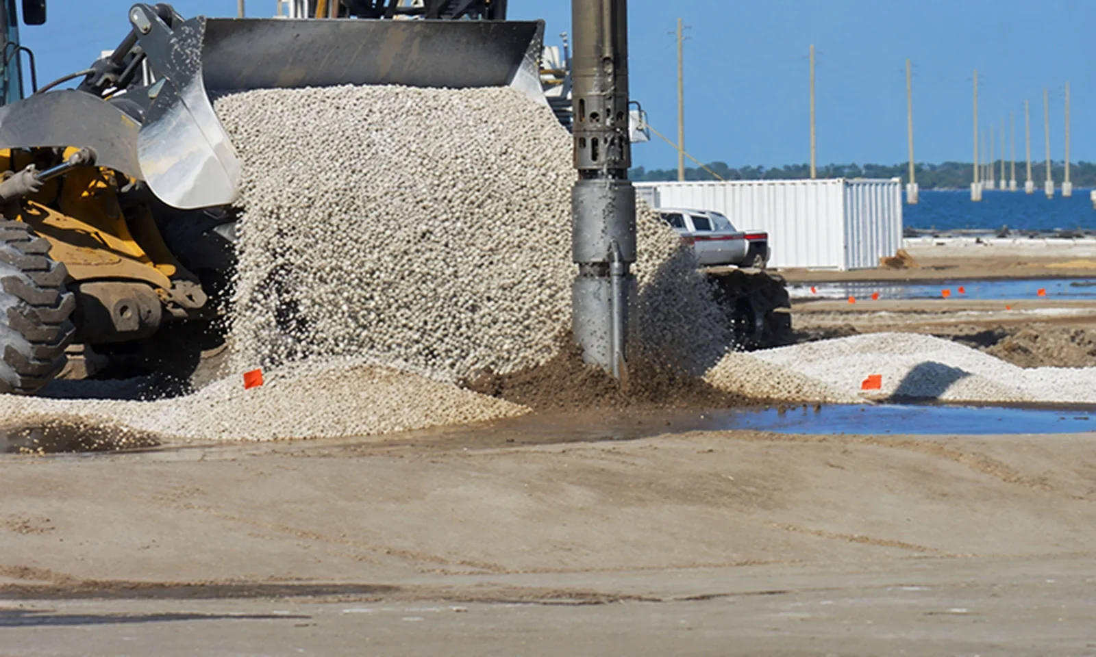
Dry stone columns

Dry stone columns

Stone-column installation using a dry method selected around the soil conditions, site constraints and approved treatment design.

Method, design checks & enquiry
Dry stone columns — system arrangement123
1Dry aggregate feed2Staged compaction3Stone column
01

Prepare the location

Confirm the treatment grid, working platform and approved installation method.

02

Install & compact

Introduce and compact stone in the specified stages to form the column.

03

Check treatment records

Review material use, installation records and project-specified verification.

Design checks: ground report, groundwater, adjacent structures, access and project-specified verification.
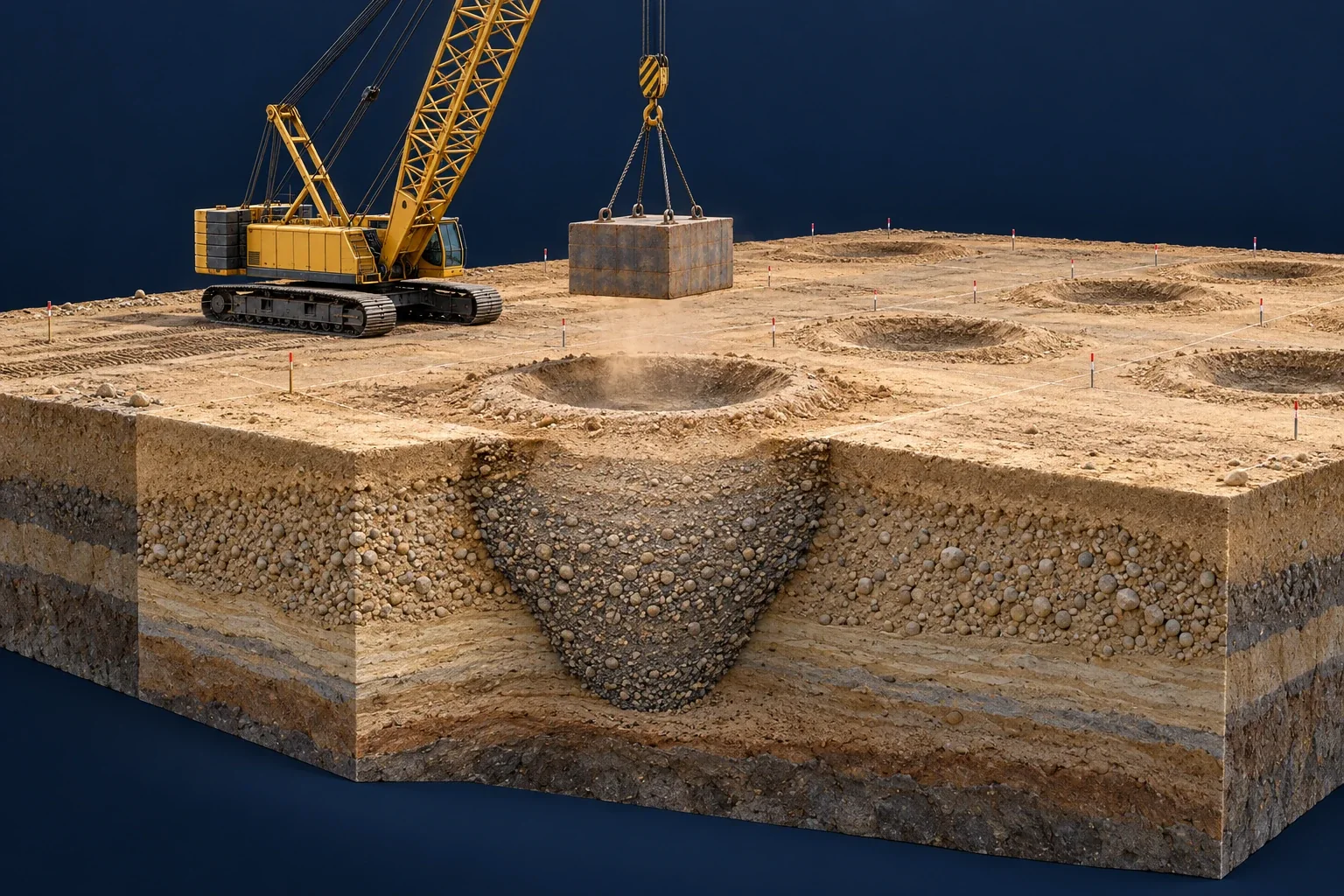
Dynamic compaction

Dynamic compaction

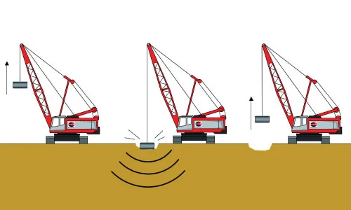
Controlled surface impacts improve suitable ground, subject to vibration and nearby-structure constraints.

Method, design checks & enquiry
Dynamic compaction — system arrangement123
1Heavy tamper2Repeated surface impacts3Ground densification
01

Trial & plan

Define the trial, impact grid, exclusion zone and monitoring.

02

Apply impacts

Apply the approved drop sequence and manage surface craters.

03

Verify response

Verify improvement using specified field tests and monitoring records.

Design checks: ground report, groundwater, adjacent structures, access and project-specified verification.
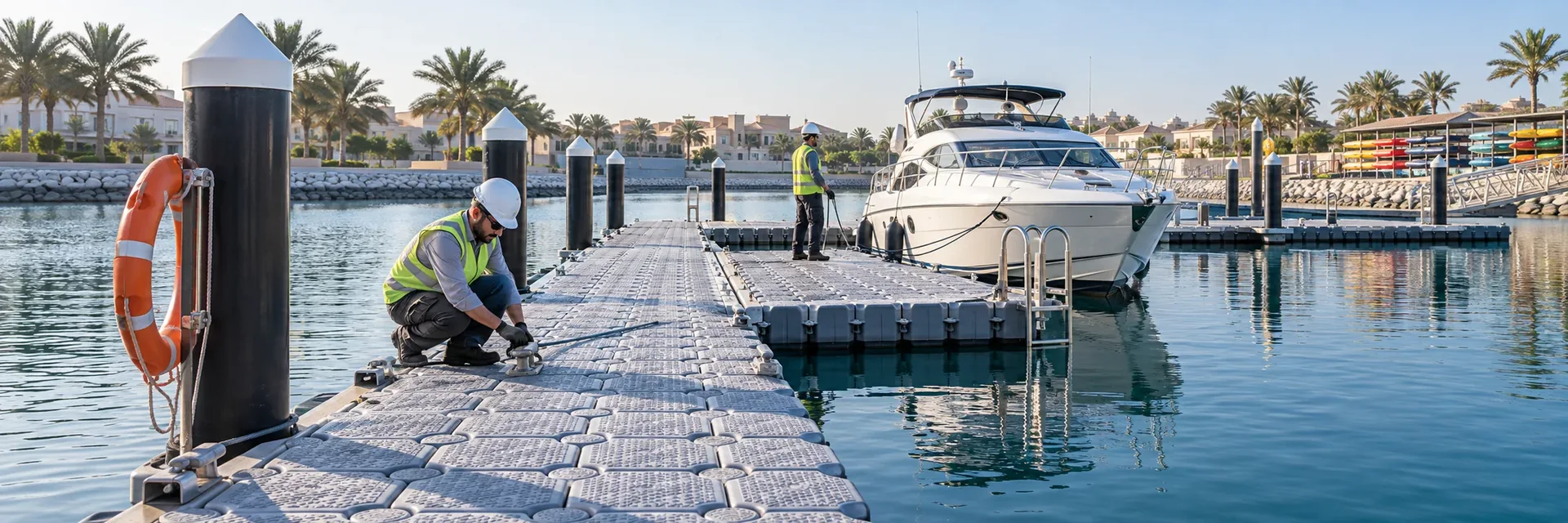
Floating marine systems

Floating marine systems

Floating docks, walkways and platforms configured for site conditions, access and mooring requirements.

Method, design checks & enquiry
Floating marine systems — system arrangement123
1Floating platform2Mooring system3Water-level variation
01

Assess & configure

Review water conditions, use, access and environmental constraints.

02

Assemble & anchor

Assemble specified units and install the engineered mooring system.

03

Inspect & hand over

Inspect connections, access and safety features and establish maintenance requirements.

Design checks: ground report, groundwater, adjacent structures, access and project-specified verification.
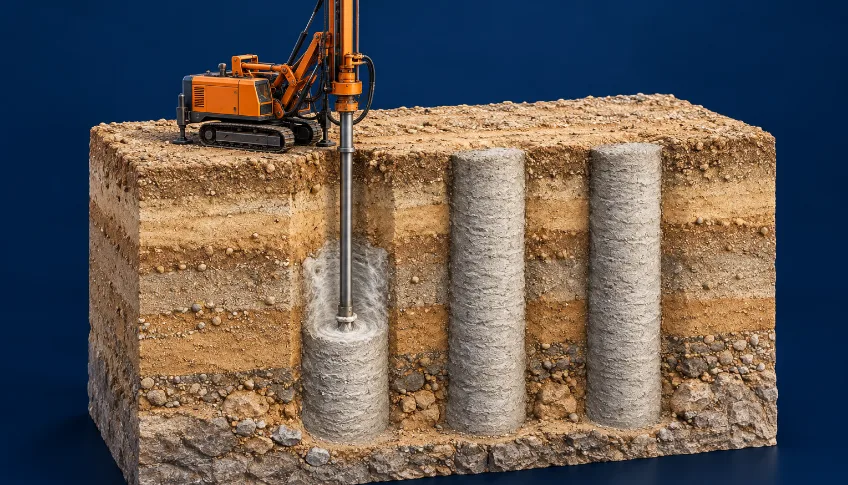
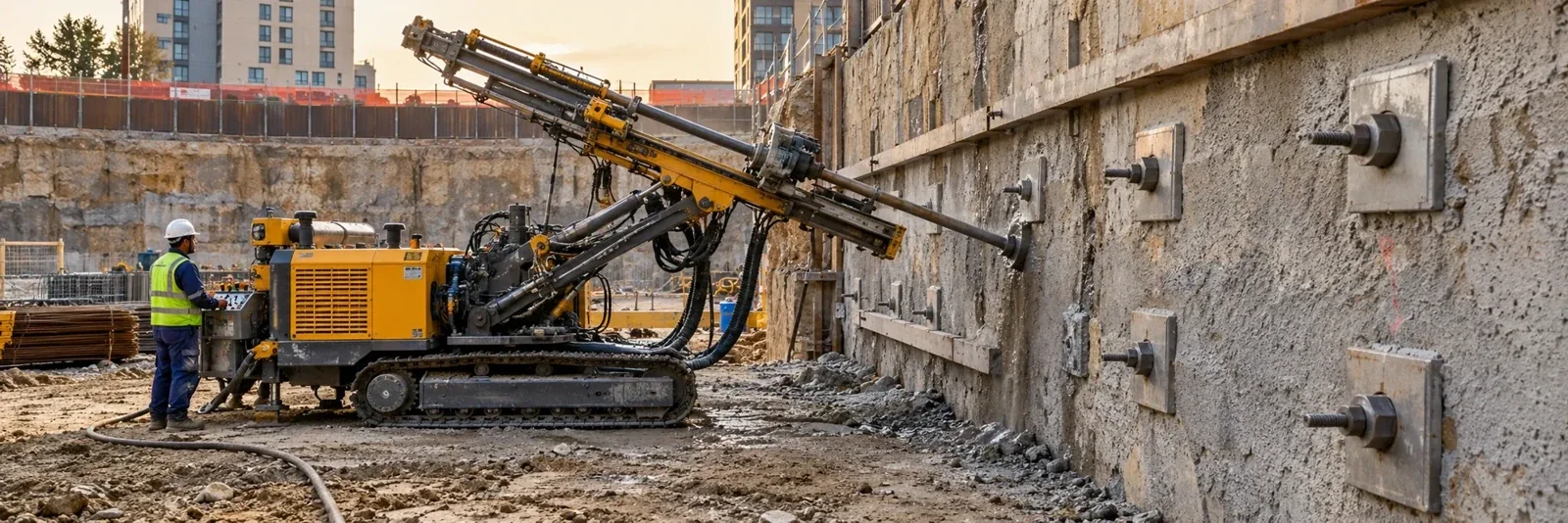
Ground anchors & soil nailing

Ground anchors & soil nailing

Reinforced ground elements support retention or soil stabilization; anchors and passive nails have distinct designs.

Method, design checks & enquiry
Ground anchors & soil nailing — system arrangement123
1Retaining face2Inclined reinforcing elements3Stable ground
01

Drill & install

Drill to the approved inclination and geometry with clearances.

02

Grout & connect

Install reinforcement, grout and connect to the specified facing or retention system.

03

Test & monitor

Perform specified proof tests; stress anchors where applicable and monitor.

Design checks: ground report, groundwater, adjacent structures, access and project-specified verification.
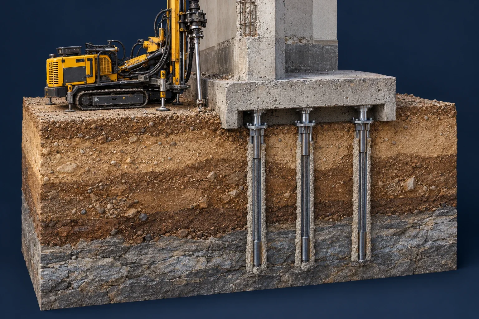
Grouting & jet grouting

Grouting & jet grouting

Targeted injection for sealing, void filling or ground improvement using a specified grout and procedure.

Method, design checks & enquiry
Grouting & jet grouting — system arrangement123
1Injection tube2Treatment zone3Controlled grout delivery
01

Investigate & trial

Define the target, grout mix, trial and monitoring plan.

02

Controlled injection

Use the selected permeation, compaction or jet-grouting method with controlled pressures and volumes.

03

Record & verify

Review records and complete specified strength or permeability checks.

Design checks: ground report, groundwater, adjacent structures, access and project-specified verification.
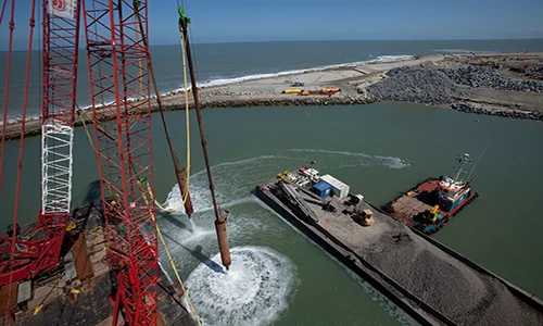
Micropiles

Micropiles

Small-diameter reinforced grouted piles for restricted access or limited headroom.

Method, design checks & enquiry
Micropiles — system arrangement123
1Steel reinforcement2Grouted bond zone3Connection to foundation
01

Drill

Select drilling and bore support for the ground and access conditions.

02

Install & grout

Install reinforcement and grout using the approved sequence.

03

Verify

Record pressures and volumes and perform specified verification tests.

Design checks: ground report, groundwater, adjacent structures, access and project-specified verification.
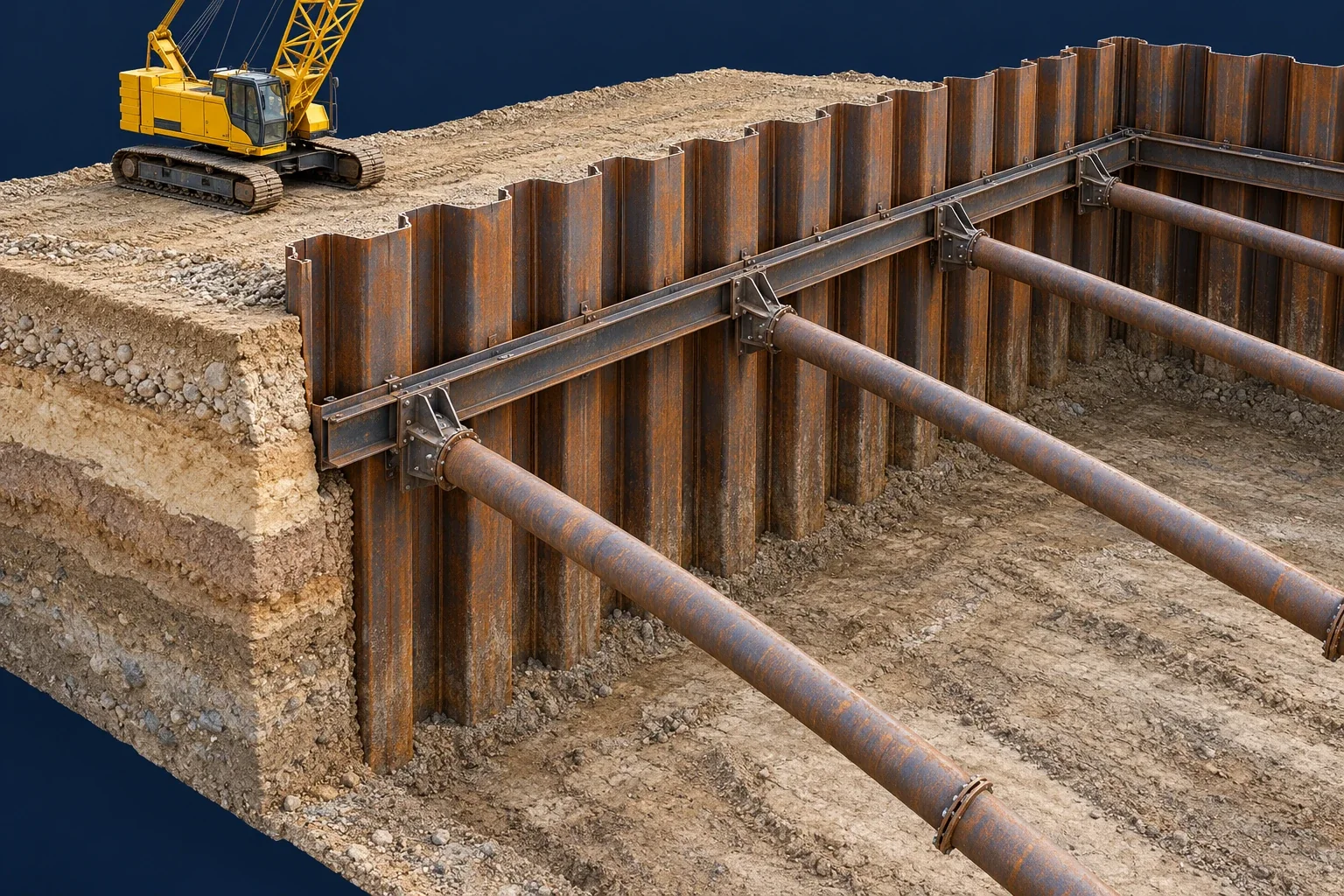
Offshore stone columns

Offshore stone columns

Ground improvement for suitable marine settings, coordinated with marine access, positioning and the approved treatment design.

Method, design checks & enquiry
Offshore stone columns — system arrangement123
1Marine positioning2Seabed treatment3Compacted aggregate
01

Plan marine operations

Review marine access, working arrangements and environmental requirements.

02

Position & install

Control positioning and installation using the project-specific marine method.

03

Record & verify

Maintain position and treatment records and undertake the specified tests.

Design checks: ground report, groundwater, adjacent structures, access and project-specified verification.
Sheet piles & steel shoring

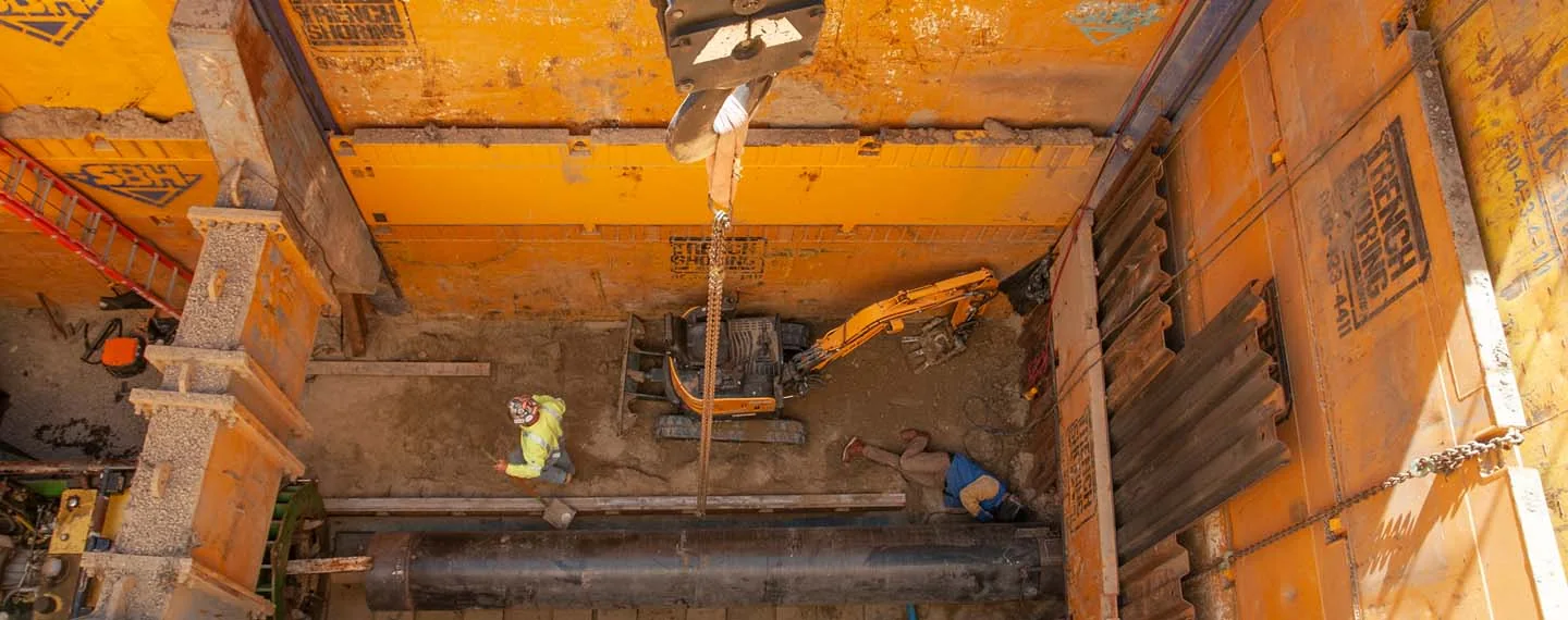
Sheet piles & steel shoring

Steel elements retain excavation sides with an engineered support arrangement.

Method, design checks & enquiry
Sheet piles & steel shoring — system arrangement123
1Interlocking steel profiles2Retained ground3Excavation side
01

Set out

Confirm utilities, boundaries and installation constraints.

02

Install

Install specified steel elements to the approved line and embedment.

03

Support & monitor

Install lagging or bracing as specified and coordinate excavation and monitoring.

Design checks: ground report, groundwater, adjacent structures, access and project-specified verification.
Slide rail & strut systems

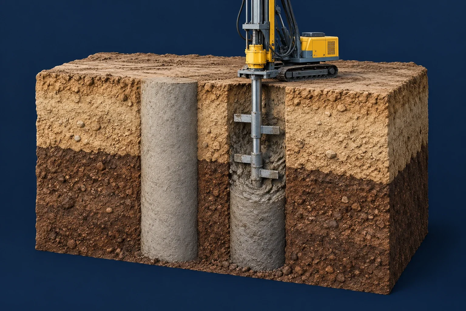
Slide rail & strut systems

A staged excavation-support system with panels, rails and struts configured for the project’s temporary-works requirements.

Method, design checks & enquiry
Slide rail & strut systems — system arrangement123
1Sliding panels2Horizontal struts3Supported trench
01

Plan the support

Coordinate the support design with excavation dimensions, nearby assets and access.

02

Install in sequence

Install the specified panels, rails and struts with the approved excavation sequence.

03

Inspect & recover

Inspect the system and coordinate recovery with backfilling and the approved method.

Design checks: ground report, groundwater, adjacent structures, access and project-specified verification.
Deep soil mixing & soil-cement stabilisation

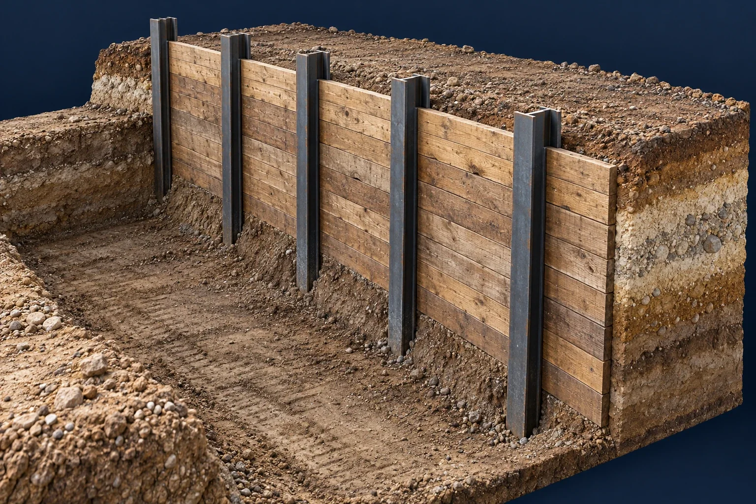
Deep soil mixing & soil-cement stabilisation

Mixing suitable ground with a designed cementitious binder to create treated soil meeting the project-specific requirements.

Method, design checks & enquiry
Deep soil mixing & soil-cement stabilisation — system arrangement123
1Mixing tool2Binder introduction3Treated soil column
01

Assess & trial

Assess ground conditions and the project-specific binder and mixing requirements.

02

Mix & control

Control the approved mixing process and record treatment parameters.

03

Sample & verify

Use the specified sampling and acceptance tests to verify the treated ground.

Design checks: ground report, groundwater, adjacent structures, access and project-specified verification.
Soldier pile systems

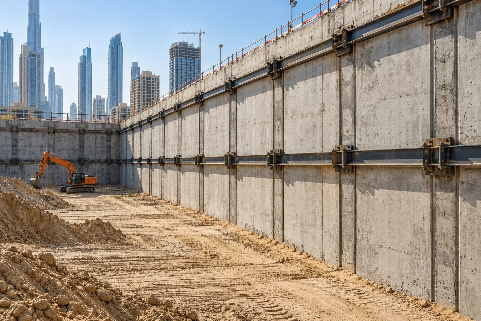
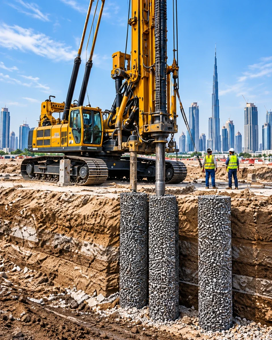
Soldier pile systems

Steel soldier elements and the specified infill retain suitable excavation faces as the excavation progresses.

Method, design checks & enquiry
Soldier pile systems — system arrangement123
1Steel soldier elements2Lagging between elements3Retained ground
01

Install elements

Install soldier elements to the approved line and embedment requirements.

02

Place infill & supports

Coordinate the specified infill and supports with staged excavation.

03

Verify the sequence

Inspect alignment, support connections and monitoring requirements.

Design checks: ground report, groundwater, adjacent structures, access and project-specified verification.
Vibro replacement stone columns

Vibro replacement stone columns

Compacted aggregate columns improve suitable ground and help control settlement.

Method, design checks & enquiry
Vibro replacement stone columns — system arrangement123
1Compacted aggregate2Treatment spacing3Surrounding soil
01

Set out & penetrate

Establish the grid and selected wet or dry installation method.

02

Place & compact

Place aggregate and compact in controlled stages.

03

Verify improvement

Review depth and aggregate records and complete specified verification tests.

Design checks: ground report, groundwater, adjacent structures, access and project-specified verification.

Vibrocompaction — offshore & land

Vibrocompaction — offshore & land

Deep vibratory treatment densifies suitable granular soils on land or offshore.

Method, design checks & enquiry
Vibrocompaction — offshore & land — system arrangement123
1Vibrating probe2Densified granular soil3Treatment grid
01

Plan treatment

Confirm soil suitability, treatment depth and verification plan.

02

Vibrate in stages

Carry out the approved penetration and withdrawal sequence.

03

Check density

Compare pre- and post-treatment field tests against acceptance criteria.

Design checks: ground report, groundwater, adjacent structures, access and project-specified verification.

Wet stone columns

Wet stone columns

Stone-column installation using water-assisted methods where suitable, with planned water and spoil management.

Method, design checks & enquiry
Wet stone columns — system arrangement123
1Water-assisted penetration2Aggregate placement3Returned water collection
01

Plan water management

Review the treatment design, water supply and handling of returns.

02

Form the column

Use the approved installation sequence to introduce and compact stone.

03

Verify the treatment

Record the treatment and carry out the specified verification.

Design checks: ground report, groundwater, adjacent structures, access and project-specified verification.

FROM OUR PROJECT REGISTER

Companies in our project portfolio.

AUTHORITIES & FREE ZONES

The UAE construction ecosystem.

LET’S START ON SOLID GROUND.

Discuss your scope, site programme and mobilisation requirements directly with our team.

Request a quote →